Aller au contenu


Photo

Inverse Kinematics


  • Veuillez vous connecter pour répondre
22 réponses à ce sujet

#21 Sandro

Sandro

    Pilier du forum

  • Modérateur
  • PipPipPipPipPip
  • 1 262 messages
  • Gender:Male

Posté 24 avril 2024 - 08:20

Have you checked that it is not just due to some perspective effects? (I don't think so, but it's hard to be sure from the video)


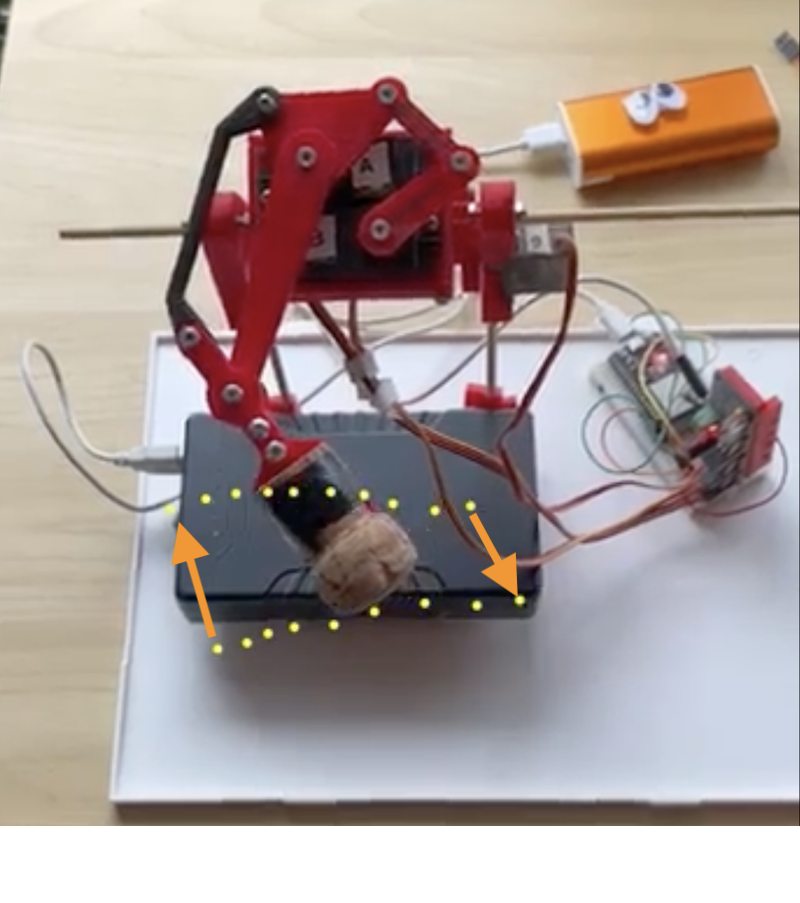
Also, I think that if you want to really study the trajectory, you should try to attach your leg in a more stable manner (I think you get significant error just from the trembling).

Otherwise, I think any of your guesses is possible.

To check, I would suggest :

A) get a stable fixation for your leg, so results are reproductible

B) redo the same trajectory : if you get something significantly different, then either your servos or your assembly is quite unstable. If you get the same trajectory, go to C

C) do again the qualibration of the servos : if your trajectory is different, then your calibration is not precise enough. If you get the same trajectory, then go to D

D) change the motors (and recalibrate) : if the trajectory changes, then the motors are probably not very accurate (ie they don't move exactly by the amount they are supposed to, it might be a low quality potentiometer inside for example). If you still get the same trajectory, then it's either the lenght of your parts, or your code that is wrong.


Aidez-nous à vous aider : partagez toutes les informations pertinentes : description précise du problème, contexte, schéma de câblage, liens vers la documentation des composants, votre code (ou encore mieux un code minimal reproduisant le bug), ...

Vous recevrez ainsi plus de réponses, et elles seront plus pertinentes.


#22 TNERA

TNERA

    Membre occasionnel

  • Membres
  • Pip
  • 102 messages

Posté 27 avril 2024 - 03:17

Yes, now that you both point it out, I believe much of the in-accuracy of the horizontal lines are probably due to the shaky fixture the leg is mounted on. I as also only quickly "eyeballing" the point at the end of the actuator. It would would be much better example if I put a pen on the foot like Oracid did.


The one thing I find interesitng appears in both my example and Oracids.  That is, I believe the "space" or surface that the actuator can reach is warped on the edges.  in Oracid's case, you can see the verticals are tilted out.  in my example they are shifted or tilted to the left.  This is what I think may be an artifact of these parallelogram or Scara type mechanisms.


Oracid-4bar.png


Mojo5-Ik-shift.png


I think to completely understand the mathematical / geometric mapping, it would be necessary to plot out the full usable space.  Just kind of interesting to me.


Thanks Oracid, Sandro, for your input.


#23 Oracid

Oracid

    Pilier du forum

  • Modérateur
  • PipPipPipPipPip
  • 6 774 messages
  • Gender:Male

Posté 28 avril 2024 - 06:33

My mechanism is very symmetrical and the precision is given by the precision of Lego. On the other hand, the use of non-Lego servos means that the 2 parallelograms are not perfect. This results in a trapezoid instead of a rectangle.
In your case, there is undoubtedly a virtual symmetry, but it is very difficult to understand because your mechanism is more complex. The difference between the left and right sides is perhaps due to the imprecision of this symmetry.
Mainly, I think the irregularity of the design is due to the use of 3D printing parts which are less precise than Lego.
 
In any case, your last video had 10 times more views than my last quadruped.
 
Keep going, you're on the right path.    :fans:


2 utilisateur(s) li(sen)t ce sujet

0 members, 2 guests, 0 anonymous users