Aller au contenu


Photo

Inverse Kinematics


  • Veuillez vous connecter pour répondre
22 réponses à ce sujet

#1 TNERA

TNERA

    Membre occasionnel

  • Membres
  • Pip
  • 102 messages

Posté 31 mars 2024 - 03:06

Hi All,

It has been a while since we last talked Inverse Kinematics!  I have been working on a new quadruped and find myself making these calculations again. This time, I had ChatGPT to help and hinder my progress - but that is a different topic!!  :dash2:

I have a version of code that is somewhat working.  For every bug I found, I created another.  I give an explanation (from my blog), pictures, and code.  please take a look and give me some feedback.  Much appreicated!

- did I miss some simplification?

- easier way to do things?

- something to be carefull with?


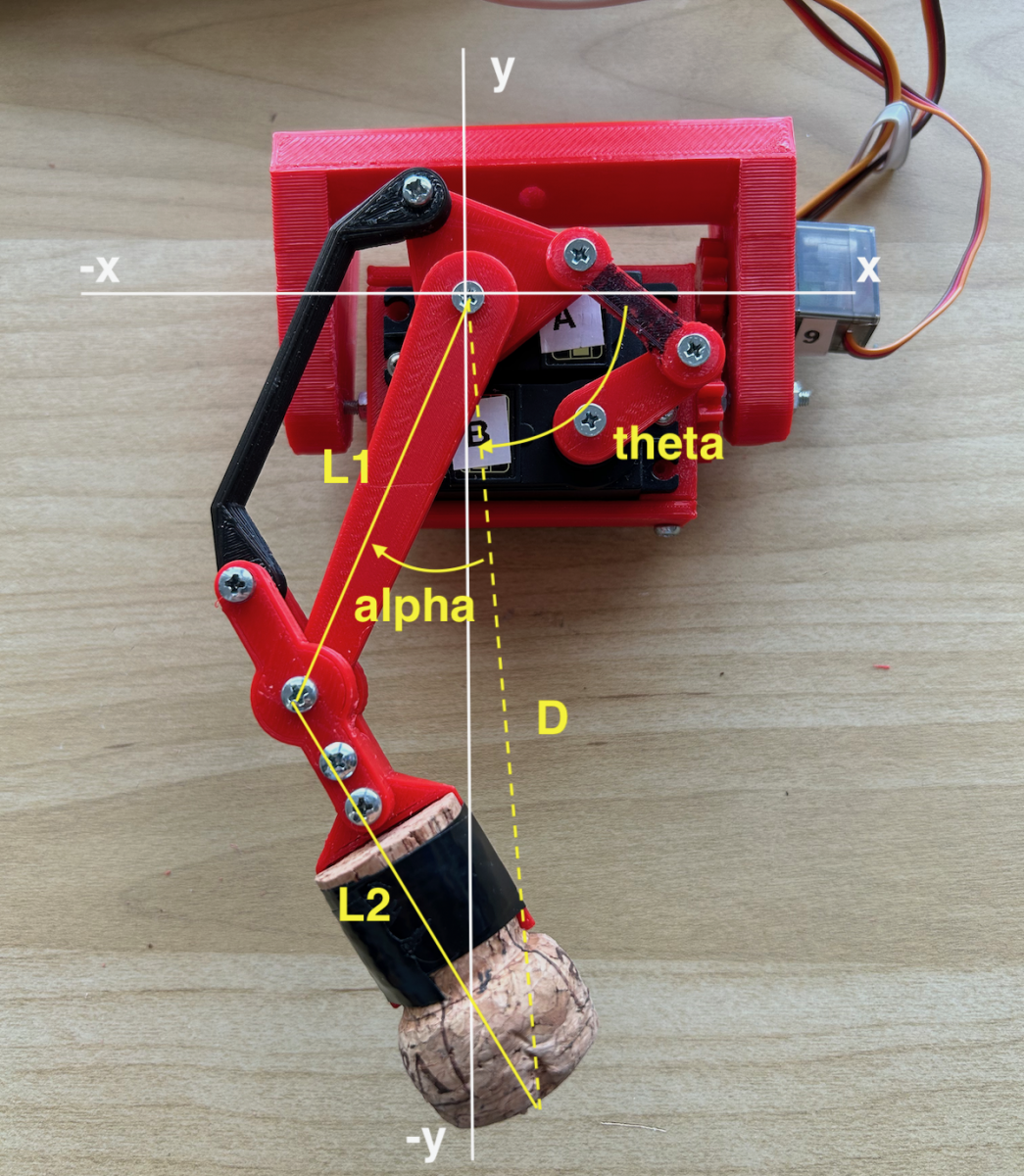
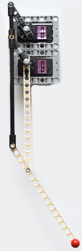
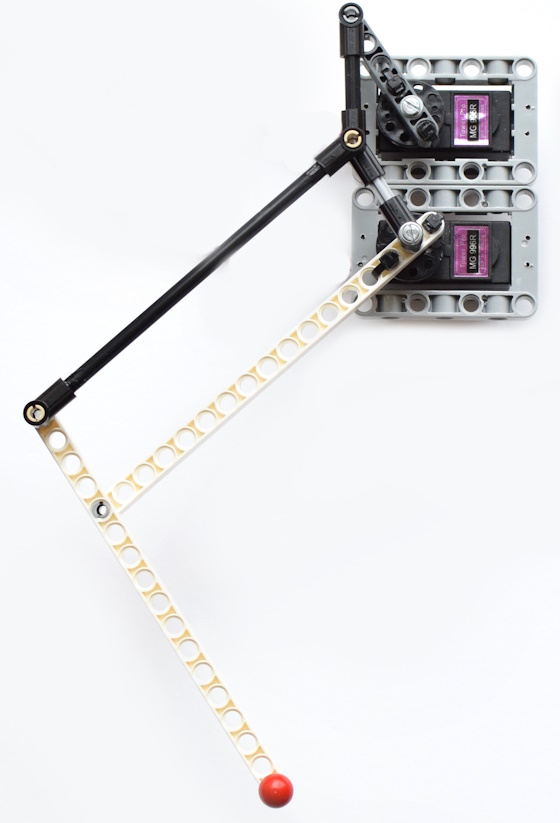
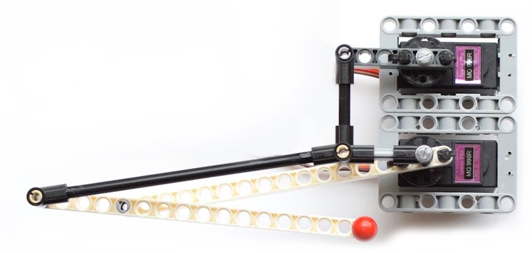
For  Mojo5, I've chosen to use two MG995 servos, arranged in a stack. One servo is responsible for the 'hip' motion, and the other controls the 'knee.' The crux of IK in this setup is to map a target position within the coordinate plane to specific angles for these servos. To streamline the calculations, I've made a series of strategic design decisions. The lengths of the leg segments, L1 and L2, are set to be equal, each measuring 70mm. The hip servo is positioned as the origin point of our coordinate system. The mechanism for the knee is somewhat intricate, primarily because the servo controlling it is not mounted directly on the leg. Additionally, I've introduced a concept of 'yaw' movement along the z-axis, although, for the time being, our IK calculations will focus solely on movements within the x and y axes.
 
When it comes to calculating the necessary angles through IK, the approach is to visualize a triangle formed by the leg segments. Given that L1 and L2 are of equal length, this triangle is always isosceles. While this detail may seem minor at first, it becomes crucial when applying the Pythagorean theorem—a^2 = b^2 + c^2—to determine the distance (D) between the endpoints of the leg segments. This distance is key to assessing the feasibility of reaching a given target (x, y) position. To ensure reachability, D must not exceed the sum of the lengths of the two leg segments, or in other words, D <= 2*L.
 
Calculating the Hip Angle (Theta1)
 
To determine the hip angle, one must sum two distinct angles. The initial angle is formed between the horizontal axis and the target point (x,y) at the end of line D in our coordinate system. This can be calculated using the ArcTangent function, specifically arctan2(y/x) in standard practices. However, in my application, I employ arctan2(-y/x). The choice to use a negative y value due to my y values will consistently fall below zero. An alternative approach could involve taking the absolute value of the ArcTangent result to ensure a positive angle.
 
Following this, it's necessary to find the interior angle between line D and leg segment L1 within our conceptualized triangle. This angle, designated as alpha, can be determined through the law of cosines. In a simplified form, the calculation of alpha is expressed as acos(D / (2*L)). By adding alpha to the previously calculated angle, we derive the hip angle. However, there's a twist due to the servo's counterclockwise incrementation: the actual Theta1 is the supplement of the sum of alpha and our initial angle, mathematically expressed as Theta1 = 180 - (alpha + theta).
 
Mojo5_leg-v3-IK-alpha.png
 
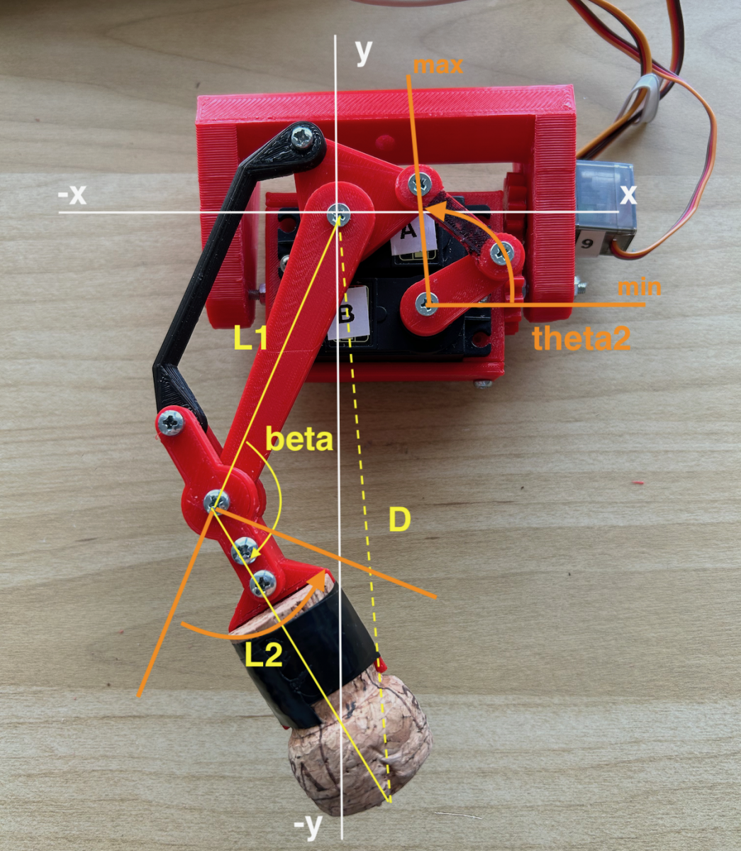
Calculating the Knee Angle (Theta2)
 
To calculate the knee angle, our first step involves identifying the interior angle between the two legs, L1 and L2, which we'll refer to as beta. Once again, the law of cosines proves invaluable for this calculation. While the deeper mathematical proofs are better left to academia, the simplified formula to compute beta is given by acos((2*L^2 - D^2) / (2*L^2)). This equation allows us to calculate beta, which represents the angle between the leg segments in our model.
 
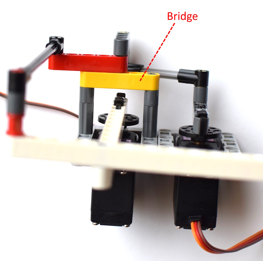
However, to translate this angle into a form usable by the servo mechanism, additional adjustments are necessary due to the servo being linked to the leg segments via cams. We must take the supplementary angle to beta. This supplementary angle, once processed through the cam system, achieves the effect of pulling the leg segments into the correct position but in a reversed direction. Consequently, we must employ the complement of this supplementary angle to align with the actual geometry and movement direction required by the servo mechanism. This raises an interesting question: could the calculation have been simplified to just beta minus 90 degrees?
 
Mojo5_leg-v3-IK-beta.png
 
Code:
 
// Function to calculate and return the servo angles given a target (x, y)
void calcIK(float x, float y, float &theta1, float &theta2) {
  float D = sqrt(x*x + y*y); // Distance from hip to target point  (x hori, y vert always neg)
  // Ensure the angle is within the robot's physical capability
  if (D > 2 * L) {
    // If the target is beyond the maximum reach, approximate values within range
    D = 2 * L;
  }

  float theta = atan2(-y,x); // Angle to target from horizontal, need pos angle its upside down.
  float alpha = acos(D / (2*L)); // Angle between leg segments for target

  // For an inverted servo, use the complementary angle
  theta1 = 180 - ((theta + alpha) * (180.0 / M_PI)); // Adjusting theta1 for the inverted servo
  
  // Beta & Theta2 calculation, knee indepedent of hip
  float beta = acos((2*L*L - D*D) / (2*L*L)); //interior angle between L1 and D
  // Theta2 subtract from 180 to invert angle (complment); bisect beta for independent; adjust for servo rotation
  theta2 = (180 - (beta * (180.0 / M_PI) / 2)) + ADJUST_B;

  Serial.printf("D: %.2f, Theta: %.2f, Alpha: %.2f, Theta1: %.2f, Beta: %.2f, Theta2: %.2f\n",
          D, theta * (180.0 / M_PI), alpha * (180.0 / M_PI), theta1, beta * (180.0 / M_PI), theta2);
}


#2 Oracid

Oracid

    Pilier du forum

  • Modérateur
  • PipPipPipPipPip
  • 6 774 messages
  • Gender:Male

Posté 01 avril 2024 - 07:12

You gave me a headache last night.   :bad:
 
It's really too complicated for me, but I'll think about it.
It's going to take me a lot of time just to understand your calculation.
 
I hope someone else can help you.
 
But does it work?


#3 TNERA

TNERA

    Membre occasionnel

  • Membres
  • Pip
  • 102 messages

Posté 01 avril 2024 - 08:40

oh, I didn't want to give you a headache! :no:

I have been working on this all weekend long, like a complex puzzle to solve.

You know @oracid! I first tried IK two years ago based on your calculations on your quadruped.

This time, I somewhat remembered the challenge, but used ChatGPT to help along.  That has pros/cons, Chat is currently incapable of processing both the math and the arrangement of the servos, etc. OR I can't describe it properly (might cause headaches!)  :pardon:


Does it work??


not exactly, well no. My knee angle theta2 is not correct. I realized this as I was drawing the picture.  In the code I bisect the beta angle (divide in 2) because I erroneously thought that this angle would always be parallel to the horizon, but it is obviously not. What I should be doing is taking the 'supplement angle' of it 180-beta --> this is the 'amount' of angle I need to move the servo.  However, the next complexity is that the servo moves opposite of this, so I must invert it to get its 'complement angle' 90-new_angle.  Oy!  now I have a headache!   :ignat_02:


actually, I think that will work, i will try it this morning.


In this process I have also learned a lot about the servo MAX / MIN PWM.  My servos are constrained by both the PWM max/min and the physical man/min of hitting the other servo. I have written some new code on the actual movement in order to properly 'map' the desired angle into the available motion space.


#4 Oracid

Oracid

    Pilier du forum

  • Modérateur
  • PipPipPipPipPip
  • 6 774 messages
  • Gender:Male

Posté 01 avril 2024 - 10:10

The MG995 servo is very bad. Better the MG996R !


I will try to make your design in Lego. Maybe tomorrow. Today is Easter.

To begin with, I have a hunch that your right servo arm should be parallel to the black bar.


#5 TNERA

TNERA

    Membre occasionnel

  • Membres
  • Pip
  • 102 messages

Posté 01 avril 2024 - 11:00

Yes, Happy Easter!


Yes, MG995 is not ideal, but it is what I have.


Here is an updated picture that shows the motion & restriction of the right servo arm, as well as how it translates to the knee.  It is in orange and in the code/diagram theta2 is this knee/servo. What I see by drawing this, is that I only need to take the 'supplement angle' from beta (180-beta), and that should be the correct angle for the servo.  With additional protection restrictions to keep it between min-max.


Mojo5_leg-v3-IK-beta.png


the black bar is a push rod or cam(?). it runs parallel to the hip/upper leg. it push/pulls the knee at the same rate.  It forms a parallelogram with the upper leg. The motion of the right servo arm is independent from the hip servo, that upper triangle the bar is connected to is 'free' of the hip servo, but rotates on the hip servo axis.


Here is a short video of the non-IK version moving up down. It has 370g of weight on it.


https://www.youtube....rts/_2CwU8cZ-0Q


#6 Oracid

Oracid

    Pilier du forum

  • Modérateur
  • PipPipPipPipPip
  • 6 774 messages
  • Gender:Male

Posté 03 avril 2024 - 07:34

Here is a schematic of your leg as I understood it.


TNERA01-S.jpg DSC_4228-S.jpg DSC_4231-S.jpg DSC_4235-S.jpg DSC_4232-S.jpg DSC_4236-S.jpg


#7 TNERA

TNERA

    Membre occasionnel

  • Membres
  • Pip
  • 102 messages

Posté 03 avril 2024 - 11:45

yes, yes!  that is a perfect representation.  All of the ratios of the parallelograms are correct. 

In mine, the hip length (L1) and the lower leg (L2) lengths are equal.  This makes the IK calculations a little simpler.


the bridge construction is correct as well. The two axis are aligned 'co-axial' but independent. I see it is a little more challenging in lego.  


Thanks for taking the time and pictures!  Any thoughts?


#8 Oracid

Oracid

    Pilier du forum

  • Modérateur
  • PipPipPipPipPip
  • 6 774 messages
  • Gender:Male

Posté 03 avril 2024 - 01:07

In mine, the hip length (L1) and the lower leg (L2) lengths are equal.  This makes the IK calculations a little simpler.

Yes, yes, of course ! Don't worry about that.


Basically, the principle seems to me identical to that used by Patrick and Pmdd.
I think that from a mechanical point of view, this principle is quite difficult to implement and that it is quite fragile.
Regarding your variant, I think there could be a way to simplify it.
 
I will think about it.


#9 Oracid

Oracid

    Pilier du forum

  • Modérateur
  • PipPipPipPipPip
  • 6 774 messages
  • Gender:Male

Posté 04 avril 2024 - 11:36

Here is an alternative equivalent to the previous version, but much simpler.


Transform01.jpg DSC_4239-S.jpg DSC_4240-S.jpg DSC_4241-S.jpg DSC_4242-S.jpg DSC_4243-S.jpg


#10 Oracid

Oracid

    Pilier du forum

  • Modérateur
  • PipPipPipPipPip
  • 6 774 messages
  • Gender:Male

Posté 04 avril 2024 - 05:14

My code works great with the alternative, even though the servos are horrible.
Besides, I think it works with any parallel movement.
I tried to make a very simplified code version. For more understanding of the IK() function, I put an explanation diagram.
 

Spoiler


Click me.

IK.jpg


#11 TNERA

TNERA

    Membre occasionnel

  • Membres
  • Pip
  • 102 messages

Posté 06 avril 2024 - 09:05

Ah yes!  when you apply "Oracid's Razor", simplification shall arrive!  Merci beaucoup!


This solution has a much simpler approach to solving for Angle B. I realize now that B can be solved by the triangle h-d-e.

much easier.


come other comments:

YES - this is design was inspired by @patrick 's TTR entry, I believe.  I didn't see pmdd's design up close, I just know it has crazy fast feet! :)   

YES - This is in the category of parallelogram servo/leg design. I would agree that the solution can be generalized. The parallel servo arms provide for much simpler calculation.


I am curious where you 'zero'ed or calibrated your knee servo?  what was your 90° position for that servo?


one of the issues with this design are the restrictions that must be put on the servos to keep them from going to bad positions.  I will come back to this in another post.

I wonder if these quadrupede leg designs have names?  (yet?  they should. ;) )


thanks for your wonderful solution.


#12 Oracid

Oracid

    Pilier du forum

  • Modérateur
  • PipPipPipPipPip
  • 6 774 messages
  • Gender:Male

Posté 06 avril 2024 - 11:49

thanks for your wonderful solution.

Well, I don't think this all this are so good.

If so, I will use it since a long time ago.

I will find some videos about different parallel linkages.


To find the good arms position, you must go to point x=0, y=0. This is the ligne on the setup() :    IK( 0, 0, LS, RS);            // initialyse the paw to position x=0 and y=0

Then you position the arms as you want.


#13 Oracid

Oracid

    Pilier du forum

  • Modérateur
  • PipPipPipPipPip
  • 6 774 messages
  • Gender:Male

Posté 06 avril 2024 - 11:59

Here you can see the linkage used by Patrick and Pmdd.

One joint is directly connected to a servo arm.
I think this solution is very restrictive and imposes the position and alignment of the servos.
In short, too many constraints and complex implementation.


#14 Oracid

Oracid

    Pilier du forum

  • Modérateur
  • PipPipPipPipPip
  • 6 774 messages
  • Gender:Male

Posté 06 avril 2024 - 12:08

Here is your solution, TNERA.
A servo has its arm directly connected to a joint.
Difficulty of implementation, because the parallelogram of the other servo is not obvious.
In summary, I don't see the point. The compactness maybe.


#15 Oracid

Oracid

    Pilier du forum

  • Modérateur
  • PipPipPipPipPip
  • 6 774 messages
  • Gender:Male

Posté 06 avril 2024 - 01:40

Stanford Doggo. The solution I have always followed.
A five bar (here a diamond, g=0). The hook attachment axis of the leg is independent of the motors or servos.
The advantage is that the servos can be located anywhere, on the moon if you want. The only condition is the connection by a parallelogram (with servos) between the servo and the joint.
The parallelogram is a regular 4 bar. We can use an "any" 4 bar which can be used as an association of gears, as a speed reducer/increase, but this is much more complicated and we must study the 4 bar as such.


#16 Oracid

Oracid

    Pilier du forum

  • Modérateur
  • PipPipPipPipPip
  • 6 774 messages
  • Gender:Male

Posté 06 avril 2024 - 01:54

The four bar linkage.


#17 TNERA

TNERA

    Membre occasionnel

  • Membres
  • Pip
  • 102 messages

Posté 07 avril 2024 - 11:14


My code works great with the alternative, even though the servos are horrible.
Besides, I think it works with any parallel movement.
I tried to make a very simplified code version. For more understanding of the IK() function, I put an explanation diagram.

I am still working on getting this to work on my implementation. 

-- OK Funny story. my IK wasn't working right and I had almost identical code.

I has just written a post explaining my problems.  Trying to get it be in the correct position for [0,0].

The text I wrote was clearly, not working, so I took a picture and drew it up. see below.  Well, it says 'should be here'.  I stared at it.  I got out my screw driver, repositioned the servo arm. and of course now it works. :D -where is the rolling eyes emoji!


IMG_8141.jpg


I still have one annoying problem.. for some reason my X coordinate plane is backward (pos of the left, going neg to the right).  this is odd, you didn't reverse yours, which direction is 'positive'?


#18 Oracid

Oracid

    Pilier du forum

  • Modérateur
  • PipPipPipPipPip
  • 6 774 messages
  • Gender:Male

Posté 08 avril 2024 - 07:27

 and of course now it works. :D


                 :drinks:


I still have one annoying problem.. for some reason my X coordinate plane is backward (pos of the left, going neg to the right).  this is odd, you didn't reverse yours, which direction is 'positive'?

Let's say your leg is the front right leg. Then +X is to the right and -X is to the left.

But the left servo is for the hip (femur) and the right servo is for the knee (tibia). And the values of the table are to go from +X to -X.


Now, let's say the leg is the front left leg. You must mirror the picture. Still, the +X go to the right and -X to the left.

But the left servo is for the knee (tibia) and the right servo is for the hip (femur).


This is for my linkage which is very symmetrical.

But I guess with your linkage you must invert the mechanism.


Are you still there ?  :crazy:


#19 TNERA

TNERA

    Membre occasionnel

  • Membres
  • Pip
  • 102 messages

Posté 24 avril 2024 - 06:47

Are you still there ?  :crazy:


I'm back.  :)  here are my results.  with my WORKING Inverse Kinematics (thanks Oracid!)  :yahoo:


It is still 'reversed', perhaps I am just looking at it from the wrong side?


In the video blow, it should be moving through a basic rectangle. starting from (0,-130) 

plotted_points.png


But you will notice in the video, that it is slightly skewed. I have traced out the points in yellow on the screen.   I think this is due to a combination of a) imperfection in the calibration of the servos. B) the crappy nature of these cheap servos, c) slight differences in connectors lengths, d) others...


what do you think?


https://www.youtube....rts/i0ccshGAzos


thoughts?


#20 Oracid

Oracid

    Pilier du forum

  • Modérateur
  • PipPipPipPipPip
  • 6 774 messages
  • Gender:Male

Posté 24 avril 2024 - 08:19

I think that your test bench is not stable enough and the evaluation of the positions is not necessarily correct, to draw a conclusion.
But it's not so bad if you compare with my drawing and a more elaborate test bench.


0 utilisateur(s) li(sen)t ce sujet

0 members, 0 guests, 0 anonymous users